|
Egmec Industry Co., Ltd.
|
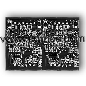
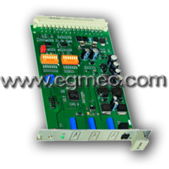
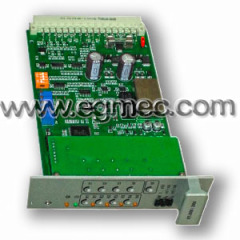
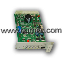
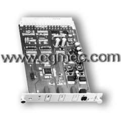
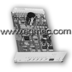
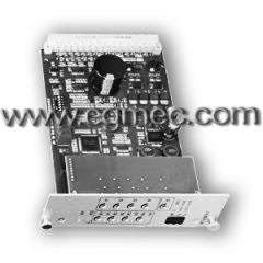
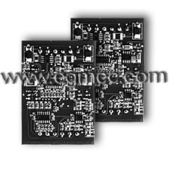
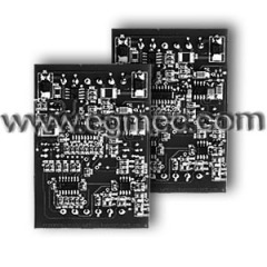
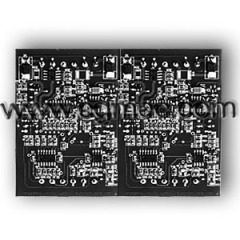
Atos Proportional Valve Amplifier
| Payment Terms: | T/T,D/P,WU |
| Place of Origin: | Zhejiang, China (Mainland) |
|
|
|
| Add to My Favorites | |
| HiSupplier Escrow |
Product Detail
1. All within the patch production process
2. Imported components
3. Enhanced anti-jamming performance
Electrical amplifier of EAB24-A-G-2X Series, ordering code:
-EAB: Electrical Atos Single Coil Amplifier
-D24: 24VDC; D12: 12VDC; D36: 36VDC
-A: Voltage signal input 0 - 10V; B:0- 20mA current signal input; C: Pulse signal input
-S: Standard amp; G: Signal generator; F: Frequency input module; P: PWM input module
-2X: Design series
General Technology:
The power supply shall be subject to the appropriate regulator or rectified and filtered. Such as the power provided by the one-way rectifier need the external 10000UF/50V electric kilns ; pulse voltage three-phase rectifier , you need an external 4700UF/50V capacitor , such as the use of switching power supply without an external capacitor . The use of power should not exceed the power limit , the external power supply circuit insurance or automatic circuit breakers ( its value depending on model) to be installed to prevent the effective protection of the amplifier when the power is reversed .
Reference power output:
Provide a reference power supply for external potentiometers, the choice of external potential timing careful not to exceed the following limitations: +5 V < 10MA , - 5V < 2MA .
Input signal:
Amplifier to accept the input voltage signal sent in the following form : external potentiometer; resistance range 1 -10K , the power is greater than 1 watt . External input signal sent by the PLC:
-10 - +10 V voltage
-5 - +5 V- voltage
Adjustments:
Amplifier adjusted by the manufacturer and with the proportional valve transfer system calibration
Bias adjustment
Dead band adjustment of the valve of the hydraulic zero electrical zero position corresponds to have the output current when the input voltage is equal to or greater than 115mv.
Ramp time to adjust:
Internal ramp generator circuit will step input signals are converted to slow increase output
(electromagnet current) from 0 to 10 v rise for the longest time for 20 seconds.
Flutter frequency adjustment:
Flutter frequency adjustment in the 100 - 500Hz range
Note that things top:
Push-pull amplifier can not be charged ; power near-line string 1A insurance to protect the amplifier ; amplifier for the open system , equipped with proportional valve should not work in the limit state .
Installation and startup:
Recommended to pick up the order given to adjust the boot
The presetting may not satisfy the requirements of special applications in the field in turn to re-adjust the bias current, gain and slope four power but to improve its performance.
Double solenoid proportional valve, according to the diagram wiring. Must provide the voltage signal - 10V - +10 V or -5V - +5 V.
Enable:
when the EN (enable) the receipt of the enable signal (usually 24VDC ) power to the amplifier start working, the state of emergency, the enable signal set to 0 , the amplifier is cutoff.
Bias adjustment:
Input voltage 0.115V signal to the amplifier power supply , and gradually adjust the bias power , but the PT4 , until the control component movement so far .
The opposite direction to turn the potentiometer until the control component stops.
Gain adjustment:
Impose the maximum input current or voltage signal to detect whether the requirements of the maximum. Clockwise dynamic the PT3 gain increases. Counterclockwise rotation PT3 gain is reduced.
Ramp time adjustment:
Clockwise slope PT1 potentiometer, increase the ramp rise time, clockwise for slope potential PT2, increase the ramp decrease time; otherwise, shorten the time, this achieve system optimal performance.

