|
Egmec Industry Co., Ltd.
|
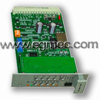
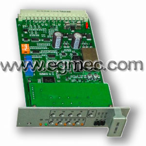
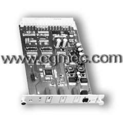
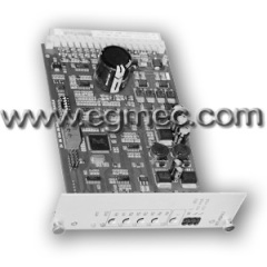
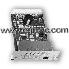
Valve Analog Amplifier
| Payment Terms: | T/T,D/P,WU |
| Place of Origin: | Zhejiang, China (Mainland) |
|
|
|
| Add to My Favorites | |
| HiSupplier Escrow |
Product Detail
1.Step signal generator, the ramp signal generator
2.With six analog relay for the start of the set value
3.Slope cut and auxiliary voltage revers
External command value:
By controlling the virtual relay setting point input 1-4 (K1 to K4) , to enable the different settings. Set the value of electricity pressure directly from the power supply, the output reference voltage ± 9V to acquire, the acquiring by an external potential. For these input mouth, ± 9V corresponds to the input value of 100%.
If these four are given value of input phase, can be used directly with ± 9V potentiometer R1to R4 adjust to four different settings. When using external power meter to enter the settings for these inputs, the internal electric the meter is not in the maximum, they will make the design of the actual input fixed value of the corresponding attenuation .
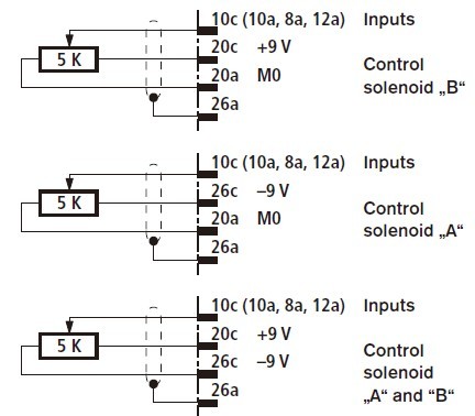
Light-emitting diodes "H1" to "H4" display settings being used value. If there is more than a set value is called at the same time, the scale a big priority.
For example: set value 1 and 3 at the same time is called, settings work, "H3," lit. There is also a direct settings 5 input, the input voltage 0 to ± 6V, ± 6V input value corresponds to 100%. Set the value of the 6 input is a differential input (0 to ± 10V).
Settings by a separate electric control part, and the benchmark potential, you must use this input is important to note: When setting the threshold voltage is disconnected or connected, the two signal lines should also be input port is connected or disconnected.
The amplifier in addition to an auxiliary voltage output a2 settings for voltage, the voltage can be a virtual relay K6 +9 V is converted to-9V.
Set the value of the input are command signal transmission control solenoid "b" exports; negative command signals to control solenoid "a" output.
Ramp times:
Adder, all the settings in accordance with its correct value and symbols (positive and negative ), the sum . Followed by the ramp generator the input step signal into a ramp output signal. Its time constant through the potentiometer "t" (for RT 3000 ) or " t1, "
To " t5 " ( by RT 3006 ) to regulate .
Given slope between is 100% set value benchmarks, and according to the DIP
Switch to different positions (J5) were approximately one second or five seconds . As
If the input of the ramp generator set value less than 100% of set value
Ramp time is reduced accordingly.
With five adjustable ramp time amplifier ( RT 3006 ) for each set value input to provide an adjustable ramp times ( potentiometers " t1, " to " t4 ") If you do not start the set value of 1 to 4 set value, the potentiometer " t5 " potentiometer " t5 " settings and of the ramp time adjustment potentiometer . With an adjustable ramp time of the amplifier (RT 3000) , when the adjustable slope between potentiometer t for all settings .
External potentiometers to adjust the slope through the terminals a14 and c14 time , but Please note : When using an external ramp time potential timing internal potentiometer ramp time must be adjusted to the maximum . Because of external the resistance of the potentiometer is switched to the resistor in parallel with the internal potentiometer
(About 500 kΩ ) , this will make the maximum slope time .
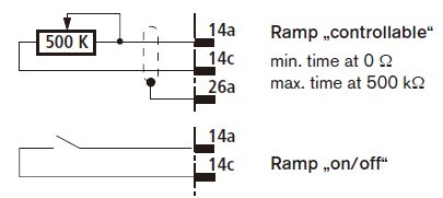
By the pull of the virtual relay K5 or via an external bridge ramp time to the minimum (about 30ms), the slope "disconnect".
Step adjustment:
The ramp generator, the output signal at the same time to the daga instruments used in and order jump generator. When the set value voltage> ± 4%, the step signal generator outputs a polarity constant step signal, the signal added to the ramp generator output signal, and then through the power the output stage and produce a step current of 200mA, the order the current spool quickly crossed being covered area.
The initial current:
When the set signal is <± 2% (step signal has not yet work) 20mA initial current flows through the two solenoids, which is used to maintain pulse frequency, the pre-magnetization of the electromagnet, and the valve electromagnet set value input from its starting position is a quick start.
Measurement port:
Send two electric output signal of the adder as the current settings flow regulator and the amplifier front panel test point "W".
Test point "W", 6V voltage is equivalent to 100% of the input value.
Electromagnet by "IA" hole (the actual current value of the electromagnet "A") and "IB" hole (solenoid "b") measurement. Here, 1 mV , the voltage equivalent to the current of 1 mA.