|
Egmec Industry Co., Ltd.
|
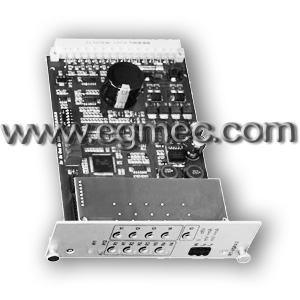
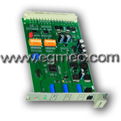
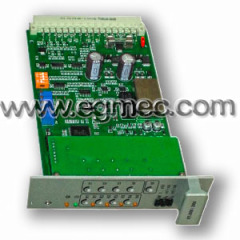
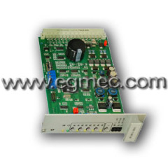
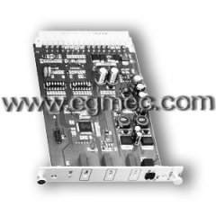
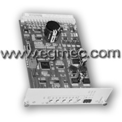
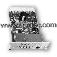
Rexroth Proportional Valve Amplifier
| Payment Terms: | T/T,D/P,WU |
| Place of Origin: | Zhejiang, China (Mainland) |
|
|
|
| Add to My Favorites | |
| HiSupplier Escrow |
Product Detail
1.T1=With a ramp time; T5=With five ramp times
2.Amplifier contains a filter capacitor
3.Powerful processor with good response
Electrical amplifier of VI-VSPA2-3X/T5 series, working principle:
Rated working voltage of 24 VDC operating voltage range of 19 ~ 35VDC , terminal 24ac for the power supply positive terminal 18ac negative side for the power , the power supply with the wrong level protection ; the same time, the amplifier already contains a filter capacitor , so the external do not need to have received an additional filter capacitor
Setting value input:
By controlling the set value input port 1-4 corresponding virtual relays (K1 to K4), you can enable different settings. Set value voltage can be directly from the power supply, the output reference voltage ± 9V acquisition, the acquiring by an external potential. For these inputs, ± 9V corresponds to 100% of the input value. 4 set value input ± 9V directly connecting the potentiometer R1 to R4 adjusts to four different settings. When using the external potentiometer or set point input to input, if the internal potentiometer is not at a maximum, they will make the settings of the actual input to the corresponding attenuation.

Light-emitting diodes "H1" to "H4" Display settings are used. If there is more than a set value at the same time is called, then label priority. For example: settings 1 and 3 is called at the same time, the settings work,"H3", lit . There is also a direct set value input port, the input voltage of 0 to ± 6V, ± 6V input value corresponds to 100%. The reference voltage setting value 1-5 M0 (measuring zero).
Set the value of the six input is a differential input (0 to ± 10V) can be set via DIP switches (see section "Display adjustment") to convert it into the current input (4 to 20 mA or 0 to 20mA). If settings are provided by a separate electric control part, and the reference potential, you must use this input, we must note: When the set value voltage is disconnected or connected, the two signal lines should also be input by or disconnected.
The amplifier in addition to an auxiliary voltage output voltage a2 is the set value, the voltage can be virtual relay K6 conversion from +9 V to - 9V.
Settings input command signal (0 to 10V, 0 to 20mA or 12mA to 20mA to) control the output port of the solenoid "b" ; negative command signal ( - 10V to 0V , 20mA to 0mA or 4mA to 12mA to output ) control solenoid "a" .
Ramp time adjustment:
All the settings in accordance with the correct value and sign (positive, negative sign) the sum of the adder. Followed by a ramp generator can be input step signal into a ramp output signal. The time constant by potentiometer "t" (T1 type) or "t1" to "t5" (T5 type) to adjust. The ramp time given is 100% of set value basis, and according to the different location of the DIP switches (J5) were approximately one second or five seconds.
The input set value is less than 100% of set value, the ramp time is reduced accordingly.
With five adjustable ramp time of the amplifier (T 5) for each set value input to provide an adjustable ramp times (potentiometers "t1" to "t4") If you do not start the settings 1-4 any of a set value potentiometer "t5" effective potentiometer "t5" settings [5] and [6], the ramp time adjustment potentiometer. With an adjustable ramp time of the amplifier (T1 type), adjustable ramp time potentiometer t for all settings.
Through the terminals a14 and c14 total adjustment from external potentiometer ramp time, but please note: When using an external ramp time potentiometer timing, the internal potentiometer ramp time must be adjusted to the maximum. Because the resistance of the external potentiometer is switched to the resistor in parallel with the internal potentiometer (about 500 kΩ) , this will make the maximum slope time .
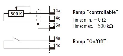
By the pull of the virtual relay K5 or via an external bridge, the ramp time to the minimum (about 30ms), the slope "disconnect".
Step adjustment:
The ramp generator [4], the output signal to the instruments used in [6] and the step generator [5] . When the set value voltage > ± 4% step signal generator outputs a constant step signal polarity of the signal added to the ramp generator output signal , and then the power output stage [7] and [ 8] a step current of 500mA , the order the current spool quickly crossed being covered area .
The initial current:
When the set signal is <± 2% ( step signal has not yet work ), the initial current of 50mA flowing through the two solenoids , which is used to maintain the pre- magnetization of the pulse frequency of the electromagnet , and the valve electromagnet set value input from its starting position is a quick start.
Measurement port:
The output signal of the adder [6] as a current setting to the two current regulator [7] and the amplifier front panel test point "W" .
Test point "W", 6V voltage is equivalent to 100% of the input value. Measuring the actual current value of the electromagnet by the hole (solenoid "a") and "IB" hole "IA (solenoid "b"). Here, the voltage of 1 mV is equivalent to a current of 1 mA.

